Stormwater Installation Guide
Transportation, Handling, & Storage
High Density Polyethylene (HDPE) pipe exhibit properties which make it ideal for use in buried applications. The pipe is lightweight making it easy to handle and manipulate by hand or with light-duty equipment. It is also very durable and generally resistant to impact, UV degradation, and most chemicals. However, as with any pipe product, there are some basic precautions that must be taken to reduce the likelihood of damage and to ensure trouble free performance.
Inspection
Once the pipe is received on the job site, an inspection, prior to final acceptance, should be completed to ensure all products are correct, accounted for, and undamaged.
Unloading & Storing
Prior to unloading the pipe, a designated area on the jobsite should be reserved for the storage of pipe materials. The area should be flat and free of debris and hazards, including large rocks, construction material, and harmful chemicals. The area should also be located far enough away from construction traffic to avoid potential contact.
Pipe is typically delivered in loose form and can be unloaded by carefully rolling the pipe onto the forks of a front-end loader, and then onto the ground. Do not use forks directly inside the pipe as it may cause damage. Alternatively, the pipe can also be removed with the use of a sling or cable.
Pipe that is equipped with bell ends should be stacked in alternating directions to reduce the possibility of bell deformation as shown in Figure 1 below:
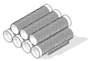
Figure 1: Proper Stacking Alignment
Moving & Stringing
HDPE and HP are relatively lightweight when compared to alternative materials; however, unloading and handling can still be dangerous. Lifting smaller diameter (4”-18”) pipe can typically be done by hand on either end of the pipe as shown in Figure 2.
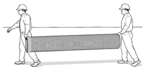
Figure 2: Lifting Small Diameter (<18”) Pipe
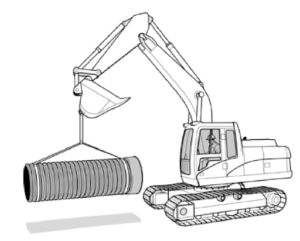
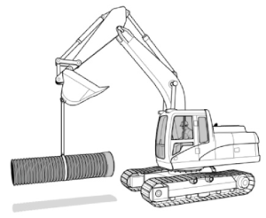
Lifting larger diameter pipe (24” & up) will typically require the use of backhoe or other equipment. The pipe should be lifted evenly with a nylon sling or cable so that the pipe won’t drag on the ground. Using bare chains or metal cables could potentially abrade the pipe and their use is not recommended.
“Stringing” or laying out the pipe along the proposed trench line is a commonly used practice which allows the pipe to be picked up and installed in one operation. The pipe should be strung out in a way that does not interfere with the excavation process. Blocks and supports should be used to prevent the pipe from rolling or deforming.
Trench Construction
First and foremost, trenches must be excavated in such a manner that the walls will remain stable under all working conditions. The trench or ditch should be wide enough to place and compact backfill around the entire pipe. • Refer to Table 2 for recommended minimum trench widths. The design engineer may modify the trench width based on site specific conditions.

Unstable Trench Walls
Due to the unstable nature of some native soils, the trench may require over-excavation to prevent collapse. In these cases, the trench width shall be determined based on an evaluation of the in-situ soil and the anticipated loading. Alternatively, a trench box may be used to support the trench walls and provide a safe work area during the pipe laying process. Depending on the trench box design, a sub-trench may need to be constructed to avoid contact between the box and the pipeline. All local, state and national safety guidelines should be followed when using trench boxes and sub-trenches. An example of a sub-trench is shown Figure 4.
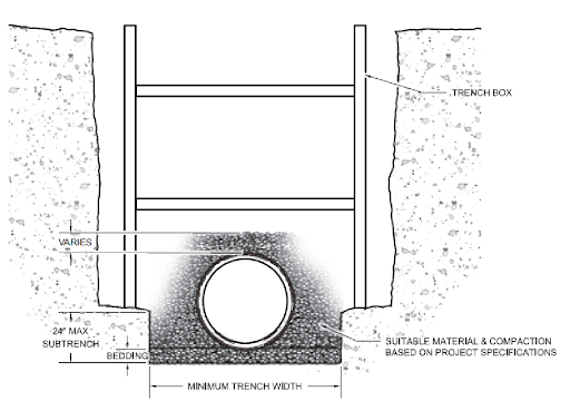 Figure 4: Typical Sub-Trench Installation
When working with trench boxes, it is critical to prevent disruption of the pipe installation while moving the trench box. If the trench box cannot be dragged without disrupting the pipe or initial backfill, it must be lifted in sections.
Water inside of the trench should be controlled before and during the pipe installation. The pipe should only be installed during dry conditions, never with running or standing water in the trench bottom. This may require control of surface and subsurface water sources by the following methods: sump pumps, wells or well points, drainage blankets, water tight sheathing, and/or sheeting. Control of water sources should be maintained until initial backfill has been installed and there is an adequate amount of final backfill to prevent floatation. The use of anti-floatation restraints such as collars or anchors may be used, if deemed necessary.
Foundations
Just like the trench walls, the soil at the bottom of the trench, referred to as the foundation, is a critical part of the installation. The foundation material must be supportive and stable, to prevent excessive settlement. In many instances the in-situ soil is stable and provides a suitable foundation. Typically, a foundation is considered stable if a person can walk over the soil without sinking in or feeling the soil move beneath them. If unstable soil, such as muck, is encountered, a typical corrective measure is to remove and replace the unstable soil. However, there are several methods of improving the foundation prior to installation depending on the soil conditions present:
- Reinforce – Soft soils are reinforced by adding dry soil, stabilizing geotextile or geogrid materials, or lime and then compacting for stabilization.
- Displace – Soupy soils are displaced by placing an overburden material such as large aggregate in the bottom until the foundation is consolidated and stabilized.
- Restore – Loose soils can be restored by compacting to a greater density.
- Remove – Existing soils that are unusable should be completely excavated and replaced with a suitable material.
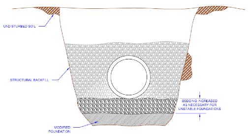
Figure 5: Modified Foundation
Bedding
The bedding material is placed in the bottom of the trench, between the foundation and the bottom of the pipe. The bedding allows for uniform longitudinal support and also distributes the load from the bottom of the pipe. The minimum bedding thickness should be a minimum of four inches for 4”-36” diameter pipe and a minimum of six inches for 42”-60” diameter pipe. Maximum particle size in the bedding material should not exceed 1½ inches. If bedding is to be used as an under drain, use a large, course, clean aggregate, not exceeding the maximum particle size.
The outer thirds of the bedding should be compacted and the middle one third portion should be loosely placed as shown in the Figure 7 below. This loosely placed area provides for uniform support at the invert.
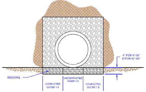
Figure 7: Bedding Placement
The bedding should be placed so that the pipe invert is at the correct grade when backfilled. It is important to note that there may be settlement of the pipe when placed on uncompacted or loosely placed soil. A backhoe bucket should not be used to press on the pipe to bring it to grade. Also, blocking or soil mounds should not be used under the pipe, as this will cause point loading.
Laying Pipe
Before pipe is laid into the trench, re-inspect the pipe for any damage and clean any debris that may have accumulated on the inside of the pipe or sealing surfaces.
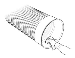
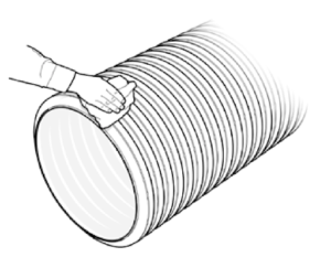
Figure 8: Cleaning Sealing Surfaces of Pipe
Pipe should also be checked to ensure that it is the correct type and size. The pipe should be lowered into the trench using slings placed in a manner that evenly supports the pipe. It is good practice to use a “tag line” when moving the pipe into position; this is a line attached to the end of the pipe, used to prevent uncontrolled pipe movement.
Pipe equipped with integral bell and spigots must be installed by inserting the spigot into the bell.
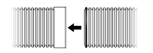
Figure 9: Integral Bell and Spigot Connection
Pushing the bell onto a spigot increases the likelihood of forcing bedding material into the joint, disrupting the gasket and severely undermining water-tight performance. With this in mind, pipe laying should begin at the lowest point of the project with spigots pointed down-grade. With the spigot ready to be inserted into the bell, remove the protective film around the gasket. Use a clean brush, cloth rag, sponge or gloved hand to apply approved pipe lube to both the gasket and the bell. Do not allow lubricated section to contact dirt or backfill. Foreign matter could adhere to the lubricated surface and compromise the joint integrity. Failure to properly lubricate the joint will adversely affect the joint performance and will increase the force needed to push the joint “home”.
Pushing the pipe together may be accomplished in a number of ways: smaller diameter pipe may be pushed together by hand or leveraged together using a spanner block and a lever as shown in Figure 10.
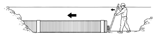
Figure 10: Installing Small Diameter Pipe
Larger diameter pipe typically requires more force to assemble which necessitates the use of machinery, such as a backhoe. One method of using a backhoe for assembly is to use the slinging strap to “pull” the spigot into the bell of a previously installed pipe, as shown in Figure 11.
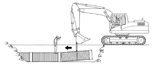
Figure 11: Installing Large Diameter Pipe with Sling
Backfilling
The backfilling process is critical to ensure long trouble-free service. The backfill and pipe function together as a structural system, forming the pipe/soil envelope, to support the soil overburden and live vehicular loads. For this reason, the backfill material and level of compaction directly impacts the performance of the pipe/soil envelope. The backfill material must have a high density as well as a resistance to migration and degradation.
Soil within the pipe/soil envelope should not contain any organic material, stumps, logs or limbs, man-made waste, debris, frozen soil, or any other unsuitable material. During the backfill process there should not be any rocks larger than the maximum particle size of 1½ inches placed in the pipe/soil envelope.
The pipe/soil envelope is divided into multiple sections, as shown in Figure 13.
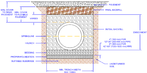 Figure 13: Typical Trench Installation
BEDDING
The bedding is placed in the bottom of the trench, between the foundation and the outside diameter of the pipe.
HAUNCH
The haunch is the area of initial backfill that extends from the bedding up to the spring line of the pipe. Getting adequate material into the haunch area, and compacting as necessary, is a critical step to ensuring a high performance installation.
INITIAL BACKFILL
Depending on the product and the application, the initial backfill extends from the spring line to the crown of the pipe or to 6 inches over top of the pipe.
FINAL BACKFILL
The final backfill is placed over the initial backfill and this material is used to build the trench up to final grade.
EMBEDMENT
The embedment refers to the zone of structural backfill around the pipe including the haunch and the initial backfill.
When beginning the backfilling process, the embedment material should be distributed and compacted in lifts evenly on each side of the trench to ensure that the pipe is not pushed out of alignment and help to prevent against elongation. Placing embedment material in the center of the pipe and allowing it to fall evenly on each side of the pipe is a method often used to maintain alignment of the pipe in the trench.
Compaction
Each section of the pipe/soil envelope should be compacted in lifts during installation. The type of material used will determine the height of the lifts and the degree of compaction necessary to achieve the desired pipe support.
Minimum Cover Height
Cover height is one of the determining factors when calculating the load carrying capacity of the installation. Minimum cover heights are dependent on the backfill material used and the expected live loads. With the minimum cover heights found in Table 5.

These cover heights assume initial backfill to the crown of the pipe for HP pipe and 6” of structural backfill over the pipe crown for HDPE pipe with an additional layer of compacted sub-base material or rigid pavement to achieve the minimum requirements.
If the pipe will experience loading from construction equipment while the project is still being constructed, temporary fill may be placed over the pipe during construction and removed after the heavy construction equipment traffic is rerouted. For heavy construction loads, between 30 and 60 tons, there should be a minimum of 3 feet of cover. For construction equipment exceeding 60 tons the minimum cover depends upon the loading foot print of the equipment. Additional fill may be required.